Thought I'd make a start at getting the clutch ready for its new springs. I am still waiting for the oil seals so I cannot finish off the sump yet.
The clutch springs are replaced to help handle the extra weight of the car.
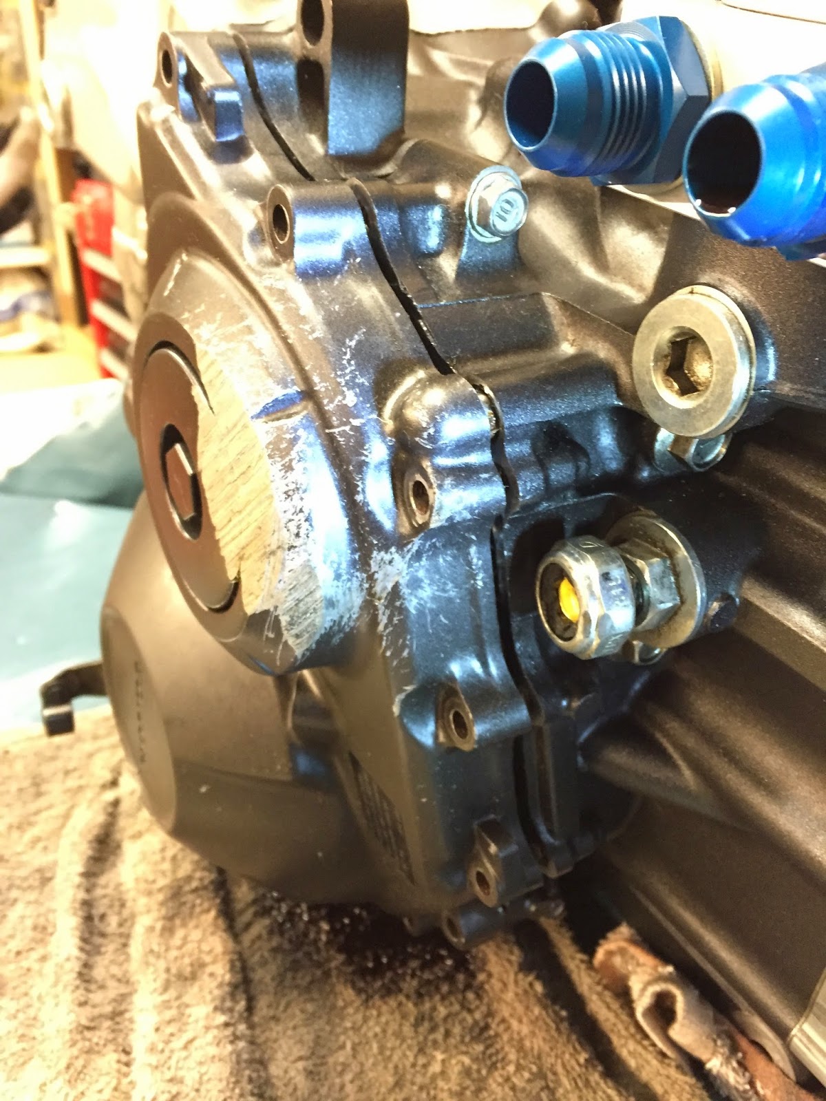
I started off noting the bolts which have the electrical connectors and washer seal. I slowly undid the bolts one either side at a time to avoid the cover warping.


At this point any oil left in the engine wants to dump itself out.

The cover was on pretty tight, and was needed a good firm wiggle slowly brings the cover off.
I turned the clutch lever anti clockwise to release the mechanism inside.

Nice and shiny again inside, its like a work of art and not an oily engine. I was careful when removing the cover as the locating pipes come up and the cover holds the pins that holds some of the gears.

I was careful not to lose the small washers. I put them in order on the engine casing so I knew which way it went back together.


The manual says don't pull out the clutch lever else it will release the spring.

Some more shiny pictures of the internals..


I removed the gear and shaft. Again noting how it goes back together.


Now I needed to remove the little circlip, I got myself a new tool to do this. The pins on the tool were too big so I had to file them down to fit first.


My new tool worked really well.

Circlip removed, now to remove the large seal.


The clutch lifter plate and shaft will now slide out. Noted where it went and placed it on the cover.


Now time time to tackle the clutch locking nut!

The locking nut is staked to stop the nut coming undone. I used a flat punch to slowly unstake it. I was careful not to damage the thread.


I used a 30mm socket, the problems now started for me. When trying to undo the run the engine turns over. So I put in gear and then the the sprocket just spins.
First off I thought I would make a bar to attach to the prop adapter to stop the engine turning over.


Some snacks before I get started..

Ok it doesn't work.. The whole engine now just wants to rotate.
After doing some research online sounds like most people use an air gun or impact wrench. I don't have one (yet). Or if the engine is fitted to the bike it sounds like you can put it in gear and put on the back brake and you can get it undone, I don't have the privilege of the engine being in a bike.

Back to the drawing board.. Before I order an impact wrench I am going to modify the bar I made to try and get it to attach to the engine mounts to stop the engine turning over, just concerned this will put too much strain on the casing.
The impact wrench will help undo but not help torque up.
Going to sleep on it and tackle again tomorrow.